Documentation Index
Fetch the complete documentation index at: https://mintlify.com/asimovinc/asimov-v0/llms.txt
Use this file to discover all available pages before exploring further.
Overview
Asimov v0 is a complete bipedal leg system for humanoid robots, featuring 12 degrees of freedom (6 DOF per leg) with an articulated toe design. The mechanical structure is built with off-the-shelf components and is fully compatible with low-volume manufacturing processes.The design utilizes an RSU (Revolute Spherical Universal) ankle mechanism that provides robust ankle actuation through a coupled motor system.
CAD Files
The complete mechanical assembly is available as a STEP file for integration into your design workflow:3D CAD File
ASV0_lowerBody.STEP - View the interactive 3D visualization of the complete lower body assembly
Accessing the 3D Model
The 3D visualization provides an interactive view of the complete leg assembly, allowing you to:- Rotate and zoom to inspect component placement
- Understand the spatial relationships between joints
- Verify mounting points and clearances
- Plan integration with upper body or torso assemblies
Naming Conventions
All mechanical components follow a standardized naming convention to ensure clarity across documentation, simulation, and hardware: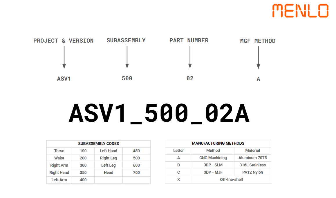
- L_ prefix for left leg joints
- R_ prefix for right leg joints
- Descriptive suffixes indicate joint type: _Pitch, _Roll, _Yaw
Joint Specifications
Left Leg
| Joint Name | Joint Type | Min Angle | Max Angle | Peak Torque |
|---|---|---|---|---|
| L_Hip_Pitch | Hip flexion/extension | -120° | +57° | 120 Nm |
| L_Hip_Roll | Hip abduction/adduction | -45° | +45° | 90 Nm |
| L_Hip_Yaw | Hip rotation | -45° | +45° | 60 Nm |
| L_Knee_Pitch | Knee flexion/extension | 0° | +86° | 75 Nm |
| L_Ankle_A | Ankle dorsi/plantarflexion | -70° | +70° | 36 Nm |
| L_Ankle_B | Ankle inversion/eversion | -70° | +70° | 36 Nm |
Right Leg
| Joint Name | Joint Type | Min Angle | Max Angle | Peak Torque |
|---|---|---|---|---|
| R_Hip_Pitch | Hip flexion/extension | -57° | +120° | 120 Nm |
| R_Hip_Roll | Hip abduction/adduction | -45° | +45° | 90 Nm |
| R_Hip_Yaw | Hip rotation | -45° | +45° | 60 Nm |
| R_Knee_Pitch | Knee flexion/extension | -86° | 0° | 75 Nm |
| R_Ankle_A | Ankle dorsi/plantarflexion | -70° | +70° | 36 Nm |
| R_Ankle_B | Ankle inversion/eversion | -70° | +70° | 36 Nm |
Notice the asymmetry in hip and knee joint limits between left and right legs. This is intentional to provide optimal range of motion during walking and running gaits.
MJF 3D Printing Compatibility
All mechanical components are designed to be compatible with Multi Jet Fusion (MJF) 3D printing technology, enabling rapid prototyping and low-volume manufacturing:Material Selection
MJF-compatible parts can be printed in PA12 (Nylon 12) or PA11 materials, providing excellent mechanical properties and durability.
Design Tolerances
All clearances and fits are designed with MJF manufacturing tolerances in mind, ensuring proper assembly without post-processing.
Surface Finish
MJF parts have a slightly textured surface finish that provides good friction characteristics for assembled components.
Key Design Features
Articulated Toe
Provides better ground contact and push-off during walking, improving stability and efficiency.
RSU Ankle Mechanism
Couples two motors to provide pitch and roll motion with reduced complexity compared to traditional designs.
Off-the-Shelf Motors
Uses standardized Encos motor models, ensuring availability and serviceability.
Modular Design
Individual joints can be serviced or replaced without disassembling the entire leg structure.
Next Steps
Motor Specifications
Learn about the specific motor models used in each joint
Ankle Mechanism
Deep dive into the RSU ankle mechanism mathematics and implementation